


In part one of the blog, I wrote about the electrical system. Both, as observed in FSX/P3D as well how we overcome it’s shortcomings. But so far we only covered the electrical sources of the Vega, namely battery, generator and ground power unit. This time I want to move on to write about the consumers of electricity.
Design principles
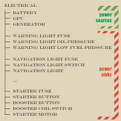
As with most other simulated components of the Vega, I try to modularize as much as possible. That allows me an easier debugging process, it’s easier to maintain code, quicker to compile, easier to expand and easier to re-use in the next project. Each system, such as lubrication, fuel, ignition, or electricity, is encapsulated in a module and each module of the simulation is governed by a parent class that holds sub-components of the system it represents. Since we’re talking about the electrical system, I have a governing class “ELECTRICAL”, which holds components such as “GENERATOR”, “BATTERY”, “LANDING LIGHT” or “STARTER MOTOR”. Each component has a set of parameters and an update function that calculates the responses. And not only is each component encapsulated in this way, but it also every switch and fuse. In this module, a sub-circuit can consist of multiple components. For example, the navigation light circuit consists of a fuse, a switch and three consumers (the lights itself). The starter circuit consists of a fuse, a starter button, the starter motor, a booster button and a booster coil.
Programming the loop
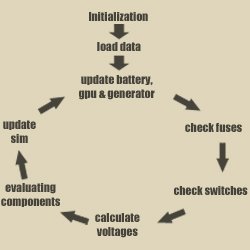
To the left you see a diagram showing the simplified update cycle of the electrical system. First, all components need to be initialized on firing up the Sim. And to do so the parameters are being loaded from the persistence file of the Vega. The cycle begins by updating the values for the power-producing components. Those are battery, generator and gpu. I wrote about these components in the last article, so just check it out if you haven’t read it yet.
Fuses and switches
The next two items in the update cycle of the electrical system are the fuses, followed by the switches. What you see on the right is a screenshot of the open fuse-box on the right-hand side of the Vega’s cockpit in the sim. Every one of these fuses is securing one of the circuits of the electrical system. The fuses have a designated current at which they melt to open the circuit and protect the connected components. In the fuse-update-cycle, the algorithm checks if the current that the connected component draws, is higher than the rating of the fuse. If so, the fuse will burn up. For a quick fix, you’ll find a box of spare fuses to replace the burnt ones.
The switch-update-cycle is checking whether a connected switch (or button) is open, or close. It takes sim-events into consideration to support keyboard commands or controller buttons that are associated with a particular event.
Voltages
Now comes the fun part, because we need to calculate the voltage of the main bus! This is done using Millman’s theorem.
The theorem states:
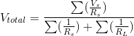
where:
- V_total is the total voltage of the circuit
- V_s is the voltage of any power generating component (i.e. battery, generator, gpu)
- R_s is the resistance of any power generating component
- R_L is the resistance of any component that draws power.
So in order to compute the voltage of the system, it is necessary to gather the resistance of all components connected to the battery circuit, as well as the voltages of each of the power sources. If you’re no stranger to math, you’ll see how the voltage will drop more significantly the lower the resistance of the load. In other words: if you engage a component that needs a lot of power (therefore draws a high current through a low resistance), you will see how the voltage of the electrical system will lower. Another thing to note is that this behavior is closely linked to the internal resistance of the power sources, i.e. the battery. A very good, new battery has a low internal resistance resulting in a lower voltage drop under the conditions described above.
Electrical components
The difficult part is done, all we need to do next is to evaluate what the electrical consumers do. But before we can do that we need to check if a component’s fuse is OK (not blown or removed) and the switch is in the “on” position if applicable. If this is true, the voltage we just calculated is passed to the component and the effect it has is evaluated. Some examples:
- if the voltage is higher than ~10 Volts, the lights will switch on
- if the oil pressure is below the low threshold or above the high threshold, the oil warning light is turning on
- the mechanical power of the starter motor is calculated, depending on the applied voltage and the efficiency of the motor. Another interesting detail about the motor is that cranking the engine is also inducing a voltage back into the system, which is reflected in the change of electrical resistance of the motor.
- etc.
Finishing up
Last part of the cycle is passing the relevant parameters back into the sim. This means updating all variables that are related to animations or effects. After that, the cycle starts again.
Conclusion
This shall conclude the chapter on our electrical system for the Lockheed Vega and I hope you found it informative.
Lastly, I need to unburden a few personal things. This September has been extraordinarily hectic for me. Not only did I take a week off to meet with family, it just so happened that my girlfriend and I received a long awaited shipment of furniture and personal effects. Consequently, we spent the last week re-organizing our home, unpacking, cleaning out and carrying heavy objects from one corner of the room to the other. Unfortunately, the progress on the Lockheed Vega suffered as a result of all of this and I cannot on good conscious release the Early Alpha this month (September). Instead, I am aiming for the end of October. To make up for it, I am hoping to include a first prototype of the complex lubrication system of the Pratt and Whitney R1340 engine!